Motivation
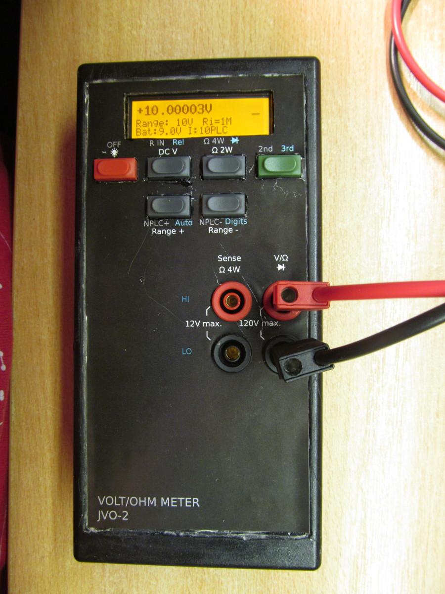
It all started with my previous project [1]. It turned out to be quite chunky box, with a fair bit of circuitry for what it is doing - measuring single voltage input. Nonetheless, despite being one of a few finished long-scale voltmeter project, it served as testbed for further development and experiments. The enclosure is really closely packed with circuitry and I wondered if it can get any smaller. On a first glance it looked quite hard, but shortly I realised it can be done, with some added benefits. Except of the obvious form factor shrink, more efficient power supply could bring less self heating, with associated faster power-up stabilization. While shrink-down voltmeter could be worthy project on its own, I decided to make it harder by adding two features - switchable input ranges and resistance measurement.While tabletop multimeters with 6 and more digits are quite common from multiple of manufacturers, vast majority of handheld multimeters do have resolution up to 60000 counts (4 and 3/4 digits), with some going to 500000 counts (5 and 3/4 digits), while 6 digits multimeters being rare as hen's teeth (Gossen Metrawatt METRAHIT 30M being exception). This imbalance exists for a reason - different use case for handheld multimeters is one factor, harder environmental conditions making stable references difficult to build is definitely another one, not to mention somehow higher consumption of precision circuitry. My device isn't here to change this in any way. I'm aware of limitations of my device and I approached it as practical example of impractical design, since chase is better than the catch.
Implementation, design goals
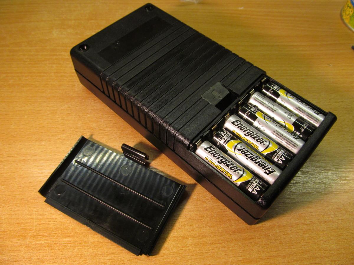
I set a few goals in previous paragraph - 6 digit measurement (with reasonable linearity and noise), battery operation, switchable input ranges. This is one boundary condition, still leaving a lot of degrees of freedom. In order to move forward I needed to define mechanical factors. Despite having 3D printer in my home lab, I opted for off-the-shelf plastic enclosure, after a bit of searching I settled down on a quite cheap enclosure [2] with 6xAA battery holder and dimensions still acceptable to be called handheld. Considering low cost, acceptable quality and good availability, another boundary condition was set. Designing handheld devices usually involves pingponging between mechanical and electrical design, this one was not an exception, so I had to return to electronics again.I set up those design goals:
* Three voltage ranges: 1V, 10V and 100V full range, bipolar. 1V and 10V ranges should have switchable input resistance - 10M and >1Gohm. (in fact I was able to acheive 1M, 10M and >1Gohm)
* Selectable integration time, at least 1, 10 and 100PLC
* Five resistance ranges - 1k, 10k, 100k, 1M and 10M full range
* Four wire resistance measurement
I set up rough block diagram:
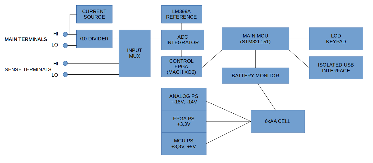
My previous voltmeter was partially designed in "throw a kitchen sink at the problem" manner. I tried to get my feet more closer to ground. Expensive LT1116 comparator was replaced with LM311 while still being suitable for this application. Opamp in integrator is OPA140, the rest of circuit employs OPA192 or OPA2192; OPA177A are used in reference circuit around LM399A. Using LM399A in reference source was tough choice. For battery powered application something like LT1236 or LTC6655 would me more sensible choice, but I decided to go a bit fancy here and used heated reference - mainly because it's design challenge.
To achieve +-10V input range (actually +-12V for overrange) and high input impedance (order of GOhm and higher) isn't that trivial exercise. In my previous voltmeter I had high hopes for LTC2057, but it's significant current noise caused me a lot of trouble at higher input impedances. There are other autozero opamps, like LTC1052 with much better parameters, but low power supply range forced me to make bootstrapped power supply for it. This is starting to dictate power supply requirements. To achieve +-12V output swing on bootstrapped output, +-18V range was needed. 36V is maximal supply voltage for OPA192 and other opamps, so I decided to derive another power rail, -14V to power the opamps. This sets supply voltage to 32V, still being fine for analog portions of circuit as well as ADC. With projected current consumptio of roughly 20mA from both +-18V rails this asks for roughly 1W of output power to analog parts. After a bit of searching I opted for ADP5070 followed by ADP7142 and ADP7182 in a basic, more-less datasheet configuration. Power to the FPGA was delivered via 3,3V LDO with shutdown, MCU is always powered on via low power MCP1703 LDOs. Last power rail is 5V for powering relays and display backlight. When device is off, MCU is dormant with minimal current consumption, but can wake-up from pushbutton press and power up FPGA and analog portions of circuit; as well as power everything down when needed. Battery voltage is monitored with high resistance resistor divider (6,2/2,4M) followed by MCP6441 voltage follower to get nice low impedance output for ADC internal to MCU. There is isolated USB interface onboard, made around CP2102 interface IC and ADUM1202 isolator.
I'd love to have at least digital domain galvanically separated from analog, but unfortunately I couldn't make power supply small and good enough, so I opted for power scheme described above. That also forced me to be more careful with grounding, decoupling and power planes placement. Going back to mechanical design I realized I can't fit everything on single PCB with dimensions given by enclosure size, so I opted for sandwich construction of two PCBs. Some circuit parts were fixed - for example user interface (display, keys) has to be on upper (main) PCB. Most logical choice would be to separate digital and analog parts on two PCBs, but I couldn't fit both analog frontend and ADC on single PCB, so I decided to have ADC on main PCB and leave analog frontend on smaller expansion PCB. Enclosure dimensions and circuit blocks division gave ma another constraint, so I could finally get to schematics drawing and PCB design.
Since I had clear idea what to do, this was relatively easy part and majority of work was done in two evenings. I opted for a bit of fun and joy (hobby projects are done for fun and joy, right?) and used minimelf 0207 resistors throughout both boards, even for some capacitors. Unfortunately decoupling capacitors are in more "boring" 0805 size format. Should there be anybody to trying to replicate my design - minimelf footprint can be populated by common and easy to solder 1206 resistor size, so you don't have to obtain not exactly common minimelf resistors.
Making it work
After PCBs were mostly populated, i discovered a few nasty layout bugs, forcing me to do quite a bit of rework and bodging. The bigger main PCB was mostly OK-ish, but analog board was half-functional even after excessive bodging. Voltmeter part was OK, but ohm current source had two ranges missing and 4-wire measurement plainly didn't work. I decided to respin the board to fix the bugs, after that I had more-less functional device, with working 4-wire resistance measurement, as well as working up to 10Mohm. Some more pictures and comments are in album [3].I realized I can have also diode test "for free", so expanded the functionality here, too.
Verification
Since the ADC has input range +-10V (with cca 2V overrange), I focused first on JVO-2 testing on this particular range.* I measured INL using Time electroncis 2003S calibrator and HP-34401A being known for quite good linearity for 6,5 digit DMM. I wasn't able to get more than 1ppm nonlinearity, see below. Anyway, this is still a bit problematic, to properly cover the INL I need higher instrument class. At least I know my device isn't completely off.

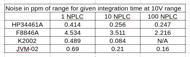
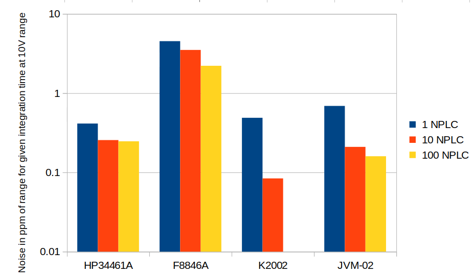
* I made quite a few measuremnts of shorted input jacks, testing for noise as per [4], fantastic resource. Fortunately there is really a lot of already measured commercial devices, so I have something to comapare against. At 10V range, for 1PLC, 10PLC and 100PLC I measured 0.69, 0.21 and 0.16ppm of RMS noise. For other ranges, see attachment 03 below. For comparison, I setup table capturing measured noise data of some other tabletop multimeters and my device

* Ohm ranges didn't get as much of treatment as voltage ones. Device was adjusted against my HP34401 on top of therange and checked with a few stable resistors I had on hand. From preliminary checks it looks like the reading correspond to each other within a few tens of ppm, but I don't call this proper test yet.
Résumé
Now I got somehow weird combo of long-scale voltohmmeter in handheld enclosure, battery powered with hungry LM399A reference.I learned a few new things, compared to what I knew before this project.
* Low local heating (and thermal design in general) is important factor in precision circuits.
* Having working ADC (as circuit on PCB) is far away from having voltmeter (as device in box) and this is heck a long way to multirange multimeter.
* Despite what MELF stands for (Mostly End up Laying on the Floor) I haven't lost single MELF resistor.
* LM399 is just really not suitable for battery operation.
After all, it was really fun project and I don't regret time and money spent on it. All sources are available on github [5]. Link in [3] contains a lot of photos with some more comments to it.
TODO
* I should verify the ohm ranges* Autorange is still not implemented. I'm not even sure I want to implement it, though.
* As the source code for MCU grew, I realized I have chosen bad firmware structure. Rewriting it to omit repeated blocks of code would be good idea, but quite a bit of work.
* Having two inputs (main input and 4W resistance sense) enables me to make ratio measurements. This is something to be examined later.
* Since I have larger FPGA on board, I can experiment with other modulation schemes than what I have now. This is very likely a thing I'm going to try.
Links
[1] - https://www.eevblog.com/forum/metrology/diy-6-5-digit-voltmeter/[2] - https://www.tme.eu/sk/katalog/?search=KM-103&s_field=1000011&s_order=desc
[3] - https://imgur.com/a/50MBxly
[4] - https://xdevs.com/article/dmm_noise/
[5] - https://github.com/jaromir-sukuba/vm_mini
Updated 15.03.2021
Back to home